Showing posts with label Concrete. Show all posts

Thursday, October 28, 2010

Handling, Storage of Timber, Precast, Steel, and Concrete Piles

Unloading. Timber piles may be unloaded by controlled roll-off. Dumping should not be permitted.

Handling. Generally treated timber piles should not be handled with timber tongs, cant hooks, peaveys, or pile chains. Piles should be handled so as to avoid puncturing or breaking through their outer treated portion. AWPA standard M4-80 permits the use of pointed tools provided that the side surfaces of the pile are not penetrated more than 1/2 in (12.7 mm). This may be difficult to control.
Treated timber piles should not be dragged along the ground.

Storage. Timber piles in storage for any length of time should be on adequate blocking and supported to avoid permanent bends. Piles should be stacked on treated or nondecaying material and with an air space beneath them. Storage areas should be free of debris, decayed wood, and dry vegetation (this presents a fire hazard) and should have sufficient drainage to prevent the piles from lying in water.

Precast Piles

Unloading. Precast piles should be unloaded by lifting them in a horizontal position. Dumping or rolling off the precast piles should not be permitted.

Handling. Precast piles should be handled with proper slings attached to designated pickup points or inserts. Impact loads should be avoided.

Storage. If precast piles are stored on blocking, it should be placed at designated support points to avoid overstressing and cracking the piles.

Steel Pipe and Tube Piles

Unloading. Controlled dumping or roll-off unloading of pipe or tube piles may be permitted.

Handling.  Sufficient pickup points should be used to avoid bends in pipe or tube piles. A closed-end pile should not be dragged along the ground with the open end first.

Steel H Piles

Unloading. H piles should be unloaded by lifting them in a horizontal position. Dumping piles should be prohibited.

Handling. H piles lifted in a horizontal position should have their webs vertical to avoid bending.
Coated H piles must be carefully handled so as to avoid damage to the coating.


Storage. H piles should be stored on adequate blocking. Nesting of piles with their flanges vertical is recommended.

Pile Shells

Unloading. Dumping of pile shells should not be permitted, but they may be roll-off unloaded.

Handling. Pile shells should be handled at all times so as to avoid permanent deformations. A closed-end shell should not be dragged along the ground with the open end first.

Storage. Pile shells should be stored out of mud or standing water. If in storage for a long period of time, shells should be protected from the elements.

Handling Cement and Concrete for Pilings

Cement

Storage. Bag cement must be stored off the ground on adequate racks and protected from the elements, especially moisture.

Concrete Aggregates

Handling. Aggregates should be handled so as to avoid breakage, segregation, and contamination.
The required gradation must be maintained.

Storage. See Concrete Production Facilities: Storage Facilities under Pile Material.


Handling Reinforcement

Reinforcement

Handling. Reinforcing steel should be handled in bundles with appropriate lifting slings located at sufficient pickup points to avoid permanent bending. Bundles should not be broken until the steel is to be used. All necessary precautions must be taken to maintain the identification of the steel after the bundles have been broken. This can be done by keeping the steel separated according to type, size, and length with a tagged piece in each stack.

Storage. Reinforcing steel should be stored off the ground on suitable racks or blocking so as to avoid permanent bends. The steel should be stored so as to prevent excessive rusting and contamination by dirt, grease, or other bond-breaking coatings.

Typical Specifications for Cast-in-Place Concrete Piles - part 2

>>>    part1

Mixing Time. Mixing time starts when the water is added to the mix and should be adequate but not excessive. Minimum mixing times vary with the size and type of the mixer and range from 1 to 3 minutes. Maximum mixing times can range from 3 to 10 minutes. For stationary mixers, minimum mixing time can be established by tests on mixer performance. For truck-mixed concrete, complete mixing requires from 50 to 100 revolutions of the drum at mixing speed. Check the manufacturer’s plate on the mixer. If, after mixing, drum speed is reduced to agitation speed or stopped, the drum should be rotated at mixing speed for from 10 to 15 revolutions just before concrete is discharged.

Elapsed Time. For normal temperatures, the total time from start of mixing to discharge should not exceed about 11/2 hours and should be reduced as temperatures increase.The mix should be discharged before 300 revolutions of the drum.

Slump. Slump tests should be made periodically in accordance with ASTM C143, Standard
Method of Test for Slump of Portland Cement Concrete, to ensure that concrete has the specified slump for proper placement in pile casings, shells, or holes. The slump for concrete as delivered to the top of the pile casing or hole should be 5 in (127 mm) for conventional concrete or 4 in (101.6 mm) for reduced coarse aggregate concrete, both with a tolerance of +2 in, -1 in (+50.8 mm,-25.4 mm). Special-type piles may require concrete having different slumps. See Special-Type Piles.
Sometimes it is advisable to check the slump just before adding the final water at the jobsite to avoid too high a slump or a wet mix.

Slump Loss. Slump loss can be caused by overmixing, hot weather, pumping through long lines, or delays in delivery and placement of concrete. Overmixing can and should be avoided. If necessary, all the mix water can be added and all mixing done upon delivery at the jobsite. This could prevent overmixing and may help in eliminating slump loss due to hot weather. If concrete is to be pumped to the pile locations, the slump should be increased without changing the water-cement ratio or concrete strength to compensate for slump loss during pumping. All preparations should be made for depositing concrete upon delivery, and delivery schedules should be arranged to eliminate delays in placing concrete.

Retempering. The addition of water to the concrete mix to compensate for slump loss resulting from delays in delivery or placing is permissible provided the design water-cement ratio is not exceeded and the concrete has not attained its initial set. Initial set is not to be confused with a false set, when the concrete appears to stiffen but can be made workable with agitation.

Delivery Tickets. A delivery ticket must accompany each load or batch of concrete. The delivery ticket is for the purchaser, but the inspector should be furnished a copy. It should include sufficient data to identify the producer, project, contractor (purchaser), truck mixer used, and specified concrete mix or strength. Other information which should be on the delivery ticket is the date of delivery, type and brand of cement, maximum aggregate size, weights of cement, sand, and coarse aggregate, type and amount of admixtures, quantity of water, time batched, reading of revolution counter and time when water was first added, volume of batch, and amount of water added by the receiver. The inspector should note the times of delivery and placement and the air temperature.

Concrete Strength. Standard cylinders for compression tests should be made periodically or as specified in accordance with ASTM C31, Standard Method for Making and Curing Concrete Test Specimens in the Field, to ensure that concrete of required strength is being furnished. The frequency for making test cylinders will vary with the job size and other factors, but generally a test set (minimum of two cylinders) should be made for each daily pour or for every 50 yd^3(38.2 m3) placed.
Also a test set should be made for each age at which compression tests are to be run. The inspector should ensure that cylinders are properly cast, handled, stored, sealed, packaged for shipment, and shipped so as not to invalidate test results. For strict concrete control, test specimens should be cast in cast-iron or tin-can molds. Although widely used, cardboard or paper molds are not recommended for molding test cylinders for strict concrete control. If cardboard molds are used, they should conform with ASTM C470, Specifications for Molds for Forming Concrete Test Cylinders Vertically. Jobsite curing or the use of cardboard molds may contribute to low strength-test results. Grout strengths for special-type piles are determined by standard cube tests in accordance with ASTM C91, Specification for Masonry Cement. (See Auger-Grout Pile, Cast-in-Place Pile, and Minipiles under Special type Piles.)

Results of Tests. The pile inspector should be furnished with copies of the results of all concrete compression tests as called for in the specifications. It is advisable to obtain 3- and 7-day results at the beginning of the job in order to detect trends in concrete strengths. The results of 7-day tests are also valuable in monitoring concrete strength trends as the job progresses so that, if necessary, remedial measures can be taken before too much concrete is placed.

Strength Variations. Variations in concrete strength as determined by standard cylinder tests are normal. Several criteria are used to determine the acceptability of variations. For example, the concrete is considered satisfactory if the average of three consecutive tests is equal to or greater than the required 28-day strength and no test falls below the required 28-day strength by more than 500 psi (3447 kPa). Another acceptance criterion is that 80 percent of the tests show strengths greater than the design strength and that not more than 1 test in 10 is less than the required 28-day strength. A third is that the average strength from consecutive tests is greater than the required 28-day strength. ACI 214.3-88 provides recommendations on evaluating concrete strength-test results.
If the test results show that concrete strength is below that specified, the cause of low-strength concrete should be investigated. Low strength could be caused by unsatisfactory materials, by improper batching and mixing, or by the use of excess water in the mix. Low cylinder breaks could also result from improperly preparing, curing, handling, or testing cylinder specimens.

Verification of Concrete Strengths. If the results of standard cylinder tests are low, cores can be removed from piles for testing. Core tests are considered satisfactory if the average of three cores is equal to or greater than 85 percent of the required 28-day strength and if no core strength is less than 75 percent of the specified 28-day strength. The results of tests on cores are normally lower than those on standard cylinders owing to microfracturing of the concrete. It should be noted that pile concrete in a long steel shell embedded in the ground will cure at a rate slower than that for test cylinders or exposed concrete. Curing conditions are ideal, but the rate of strength gain is lower than normal. Concrete strength in completed piles can also be checked by various nondestructive methods such as penetration-resistance tests. See ASTM C803, Method of Tests for Penetration Resistance of Hardened Concrete.

Typical Specifications for Cast-in-Place Concrete Piles - part 1

Design Mix. A design mix with results of tests on standard cylinders should be furnished by the contractor. Copies of these data should be made available to the inspector at the start of pile installation.

Concrete Production Facilities. Concrete may be mixed in portable mixers brought to the pile locations, but generally it will be ready-mixed. Ready-mix concrete may be (1) batched and mixed at a central plant and delivered to the pile locations in agitating or in agitating trucks (central-mixed), (2) batched at a central plant and mixed in a truck mixer in transit to or after reaching the jobsite (truck-mixed), or (3) partially centrally mixed with mixing completed in a truck mixer in route to the job or on the jobsite (shrink-mixed). The central plant may be located on the jobsite.
The concrete batch and mixing plant should be inspected for adequacy of storage facilities for materials, accuracy, and reliability of batching equipment, condition of mixing equipment, and proper operational procedures.

Storage Facilities. Cement must be kept dry whether it is stored in bulk containers or in bags.

To avoid contamination, stockpiles of aggregates that have been cleaned, graded, and prepared for batching should be on a hard, clean base with the area around the stockpiles spread with a bedding material of sand, gravel, or rock. Side slopes of stockpiles should not exceed 7 in/ft (583 mm or less per meter) to prevent segregation. Coarse aggregate should be separated by type and size gradation.
Overlapping of stockpiles should be prevented and suitable drainage should be provided.
All reasonable precautions should be taken to keep the moisture content of aggregates as nearly uniform as possible.

Batching Equipment. Concrete is usually batched by weight. Batching scales should have recent calibration and certificate of inspection and must be clean and free of interference by other objects. Separate weight-batching facilities should be provided for cement. Batch-weight recording and cutoff devices must operate accurately. The bottom of batch bins must be fully sloped in all directions. Water-metering devices, whether at a central mixing plant or mounted on a truck mixer, must be accurate and equipped with indicating dials and totalizers.

Mixing Equipment. All mixing equipment, whether stationary or truck-mounted, must be in
good operating condition. The interior of drums should be clean, and mixing blades should not show signs of wear in excess of 1 in (25.4 mm). Truck mixers must be equipped with a reliable revolution counter.

Operations. All materials must be accurately batched, and batching should be by weight. Admixtures, if required, must also be accurately measured. Mixing drums must be cleaned after each use to prevent an accumulation of hardened concrete on the blades. All washwater must be removed from the mixing drum prior to batching. Cement should be used on the basis of first in-first out. The free-water content of the aggregates should be included as part of the total mix water. Aggregates should be allowed sufficient time to drain, and it may be necessary to have a moisture meter in the sand batcher to monitor moisture content. Proper equipment and methods must be used for handling aggregates to avoid segregation and breakage. Segregation of coarse aggregate can be reduced by separating it into several size fractions and batching them separately. Finished screening of aggregates at the batcher is recommended to avoid problems of segregation and contamination.

Concrete Materials. Materials including cement, sand, coarse aggregate, and water should be inspected for compliance with specifications and accepted practice.

Cement. Cement must be of the type specified or permitted with the approval of the engineer.
Mill certificates should be furnished to show that cement conforms with the requirements of the specifications and ASTM C150, Standard Specifications for Portland Cement.Type IV cement should not be used for pile concrete. Type III, or high-early, cement may be permitted for cast-in-place concrete test piles to get a fast gain in strength. Type II or Type V cement may be specified for sulfate exposure.
Cement remaining in bulk storage for more than 6 months or cement stored in bags longer than
3months should be retested before use to ensure that it meets the requirements of ASTM C150.
Cement should not be used directly from the mill if it is still hot. The cement should be allowed to cool before using to reduce the possible occurrence of false sets.
Cement should be inspected for lumps caused by moisture. Cement bags should be inspected for rips, punctures, or other defects. If cement is to be batched by bag, the weights of bags should be spot-checked and should not vary by more than 3 percent.

Sand. Sand should be clean, sharp, well graded, and free of silt, clay, or organic material. The specific gravity and/or fineness modulus may be specified for special mixes such as reduced coarse aggregate concrete.

Coarse Aggregate. Specifications may permit gravel or crushed stone. The use of crushed rock aggregate requires more cement and sand for comparable workability. Air entrainment also improves workability. Lightweight aggregates are not recommended, and slag aggregates are not generally used. Alkali-reactive aggregates or aggregates from shales, friable sandstone, chert, and clayey or micaceous rock should not be permitted. Aggregates should be uncoated and free of silt, clay, organic material, and chemical salts. The specific gravity of the coarse aggregate may be specified. Aggregates should be well graded with a maximum size of  ¾  in (19.05 mm) and with the amounts of aggregates less than
3/16 in (4.762 mm undersize) held uniform and within 3 percent.

Water. As a general rule, mix water should be potable. It should contain no impurities which would affect the quality of the concrete. It should not have a sweet, saline, or brackish taste or contain silt or suspended solids. Very hard water may contain high concentrations of sulfate. Well water from arid regions may contain harmful dissolved mineral salts. If questionable, the water can be chemically analyzed.The quality of the water can be checked by comparing the strength of concrete reached at various ages for a mix using the water of unknown quality with the results of similar age tests on a mix made with water which is known to be acceptable. Impurities in mix water may affect both the compressive strength of the concrete and its setting time.

Admixtures. The authorized or mandatory use of admixtures will be noted on the mix design report. Special admixtures such as retarders and fluidizers may be required for pumped concrete.

Cold-Weather Operations. The minimum temperature of fresh concrete as mixed should be about 45°F (7.2°C) for air temperatures above 30°F (-1.1°C), 50°F (10°C) for air temperatures from 0 to 30°F ([1]17.2 to -1.1°C), and 55°F (12.7°C) for air temperatures below 0°F (-17.2°C). Frozen aggregate or aggregates containing lumps of ice should be thawed before being used. It may be necessary to preheat the mix water and/or the aggregate. For air temperatures between 30 and 40°F (-1.1 and 7.2°C), it is usually necessary only to heat the water to a maximum of about 140°F (60°C).
For air temperatures below 30°F (-1.1°C), the water can be heated to 140 to 212°F (60 to 100°C) and the aggregate to about 45 to 55°F (7.2 to 12.7°C). Overheating should be avoided. If both the mix water and the aggregates are preheated, it is recommended that the water be mixed with the aggregates before adding the cement to avoid a flash set. The temperature of the water-aggregate mixture should not be higher than 80°F (26.6°C) and preferably about 60°F (15.5°C).

Hot-Weather Operations. If the temperature of the concrete during mixing is above 80°F
(26.6°C), it could result in increased water demand (slump loss) or an accelerated set. The easiest way to control and reduce the concrete temperature is by using cold mix water, which can be achieved by mechanical refrigeration or by using crushed ice as part or all of the mix water. Mixing time should be kept to a minimum, and mixing drums, water tanks, and pipe should be painted white.

>>>   part 2


Wednesday, October 27, 2010

Precast Concrete Piles


Design Requirements. Adequate plant inspection reports should accompany each pile shipment, identifying the piles and certifying that they meet the design specifications including such things as the amount of reinforcing steel, 28-day concrete strength, and effective pre-stress. Piles should be marked or stamped with the date of manufacture. Inspection reports should come from an independent testing agency and not from the manufacturer.

Lengths. Precast piles will be shipped to the jobsite according to specified or approved ordered lengths. Each pile should be of the full ordered length except when sectional-type piles are permitted. Sometimes piles are ordered with sufficient extra length to permit stripping back the concrete and exposing the reinforcing steel for the pile-to-cap connection (see under Pile Installation).
Ordered lengths may be somewhat larger than anticipated driven lengths to allow for variations insubsoil conditions.

Dimensions. Piles should be of the shape and size specified. Tolerances. Piles should be straight within specified tolerances. Butt ends should be square to the longitudinal axis and free of any major surface irregularities.

Chamfers. All corners or edges of square piles should be chamfered. The width of the chamfer should be limited to about 1.5 in (38.1 mm) so that the reduction in any side dimension due to chamfer is not more than about 2 in (50.8 mm).

Damage. Check piles for detrimental cracks, spalling, slabbing, or other damage. Hairline cracksare normal but should not be too numerous.

Tuesday, October 26, 2010

Advantages and Disadvantages of Different Types of Piles


Wood piles
+The piles are easy to handle.
+Relatively inexpensive where timber is plentiful.
+Sections can be joined together and excess length easily removed.
–The piles will rot above the groundwater level. Have a limited bearing.
–Can easily be damaged during driving by stones and boulders.
–The piles are difficult to splice and are attacked by marine borers in salt water.

Prefabricated concrete piles (reinforced) and prestressed concrete piles affected by the
ground-water conditions.
+Do not corrode or rot.
+Are easy to splice. Relatively inexpensive.
+The quality of the concrete can be checked before driving.
+Stable in squeezing ground, for example, soft clays, silts and peats pile material can be inspected before piling.
+Can be re driven if affected by ground heave. Construction procedure unaffected by groundwater.
+Can be driven in long lengths. Can be carried above ground level, for example, through water for marine structures.
+Can increase the relative density of a granular founding stratum.
–Relatively difficult to cut.
–Displacement, heave, and disturbance of the soil during driving.
–Can be damaged during driving. Replacement piles may be required.
–Sometimes problems with noise and vibration.
–Cannot be driven with very large diameters or in condition of limited headroom.

Driven and cast-in-place concrete piles
Permanently cased (casing left in the ground)
Temporarily cased or uncased (casing retrieved)
+Can be inspected before casting can easily be cut or extended to the desired length.
+Relatively inexpensive.
+Low noise level.
+The piles can be cast before excavation.
+Pile lengths are readily adjustable.
+An enlarged base can be formed which can increase the relative density of a granular founding stratum leading to much higher end bearing capacity.
+Reinforcement is not determined by the effects of handling or driving stresses.
+Can be driven with closed end so excluding the effects of GW.
–Heave of neighboring ground surface, which could lead to re consolidation and the development of negative skin friction forces on piles.
–Displacement of nearby retaining walls. Lifting of previously driven piles, where the penetration at the toe have been sufficient to resist upward movements.
–Tensile damage to unreinforced piles or piles consisting of green concrete, where forces at the toe have been sufficient to resist upward movements.
–Damage piles consisting of uncased or thinly cased green concrete due to the lateral forces set up in the soil, for example, necking or waisting. Concrete cannot be inspected after completion.
Concrete may be weakened if artesian flow pipes up shaft of piles when tube is withdrawn.
–Light steel section or precast concrete shells may be damaged or distorted by hard driving.
–Limitation in length owing to lifting forces required to withdraw casing, nose vibration and ground displacement may be a nuisance or may damage adjacent structures.
–Cannot be driven where headroom is limited.
–Relatively expensive.

Bored and cast-in-place (non-displacement piles)
+Length can be readily varied to suit varying ground conditions.
+Soil removed in boring can be inspected and if necessary sampled or in-situ test made.
+Can be installed in very large diameters.
+End enlargement up to two or three diameters is possible in clays.
+Material of piles is not dependent on handling or driving conditions.
+Can be installed in very long lengths.
+Can be installed without appreciable noise or vibrations.
+Can be installed in conditions of very low headroom.
+No risk of ground heave.
–Susceptible to “waisting” or “necking” in squeezing ground.
–Concrete is not placed under ideal conditions and cannot be subsequently inspected.
–Water under artesian pressure may pipe up pile shaft washing out cement.
–Enlarged ends cannot be formed in cohesionless materials without special techniques.
–Cannot be readily extended above ground level especially in river and marine structures.
–Boring methods may loosen sandy or gravely soils requiring base grouting to achieve economical base resistance.
–Sinking piles may cause loss of ground I cohesion-less leading to settlement of adjacent structures.

Steel piles (Rolled steel section)
+The piles are easy to handle and can easily be cut to desired length.
+Can be driven through dense layers. The lateral displacement of the soil during driving is low (steel section H or I section piles) can be relatively easily spliced or bolted.
+Can be driven hard and in very long lengths.
+Can carry heavy loads.
+Can be successfully anchored in sloping rock.
+Small displacement piles particularly useful if ground displacements and disturbance critical.
–The piles will corrode.
–Will deviate relatively easily during driving.
–Are relatively expensive.

Concrete Reinforcing Bar Size/Weight Chart


BAR SIZE
DESIGNATION
WEIGHT
POUNDS
PER FOOT
NOMINAL DIMENSIONS-ROUND SECTION
DIAMETER
INCHES
CROSS-SECTIONAL
AREA-SQ INCHES
PERIMETER
INCHES
#3
.376

.375

.11

1.178

#4
.668

.500

.20

1.571

#5
1.043

.625

.31

1.963

#6
1.502

.750

.44

2.356

#7
2.044

.875

.60

2.749

#8
2.670

1.000

.79

3.142

#9
3.400

1.128

1.00

3.544

#10
4.303

1.270

1.27

3.990

#11
5.313

1.410

1.56

4.430

#14
7.650

1.693

2.25

5.320

#18
13.600
2.257
4.00
7,090

Concrete Curing Time

At 50°F (10°C)

Percentage design strength required
Type cement used in mix

        I                   II                 III
50%

6

9

3
65%

11

14

5
85%

21

28

16
95%
29
35
26

At 70°F (21°C) Days


Percentage design strength required
Type cement used in mix

        I                   II                 III
50%

6

9

3
65%

11

14

5
85%

21

28

16
95%
29
35
26

Monday, October 25, 2010

Curing of Concrete-Curing Procedures

To attain design strength, curing is a crucial part of the cast-in-place concrete process in order that the proper amount of moisture content and ambient temperature be maintained immediately following the placement of the concrete. The optimum curing cycle will take into account the prevention or replenishment of moisture content from the concrete and the maintenance of a favorable temperature for a specific period of time. During winter months, temporary protection and heat is required in conjunction with the curing process, and during summer months, moisture replenishment becomes an integral part of the curing process.
1. Apply a membrane-curing compound-eithe r by spraying or rolling on the surface immediately after the troweling process on slabs has ceased, or on walls, columns, beams, after the forms have been removed.
2. Curing by water in other than cold-weather conditions is acceptable, as long as it is continuous.
3. Waterproof paper, applied directly over the concrete surface after it has received a spray of water, is often effective.
4. Damp burlap, free of foreign substances that could leach out and stain the concrete, is also a proven curing procedure, as long as the burlap is kept moist.
5. Polyethylene sheets can be used as a blanket in much the same manner as waterproof paper, as long as its edges are lapped and sealed properly.
6. Damp sand or straw is also used on occasion, when nothing else is available. These materials must also be sprayed from time to time to maintain the moisture content.
The length of curing depends upon a number of factors, including the type of cement used and am bient temperatures. The following can be used as a guideline to determine the length of curing time.

Recommended Slumps

The Portland Cement Association recomumends the following slumps:

Component

Max. slump (inches)
Min. slump (inches)
Footings (reinforced or not)

3
1
Foundation walls

3
1
Substructure walls

3
1
Caissons

3
1
Beams and reinforced walls

4
1
Building columns

4
1
Pavements and slabs

3
1
Mass concrete
2
1


Slump Test

Slump, as it relates to concrete, is a measure of consistency equal to the decrease in height, measured to the nearest
1⁄4 inch (6 mm) of the molded mass immediately after it has been removed from this molded mass created by the “slump cone.”
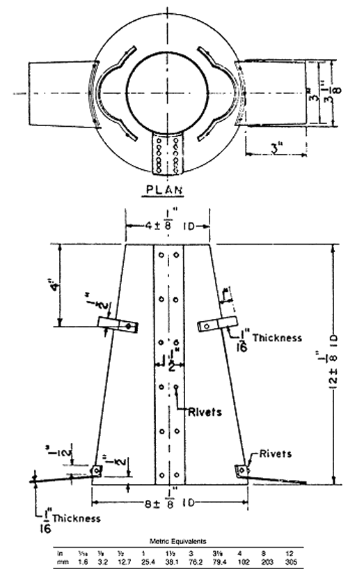
The mold is in the form of a frustum (part of a solid cone intersected by the use of parallel lines) 12 inches (2.5 cm) high, with a base diameter of 8 inches (2 cm) and a top diameter of 4 inches (1 cm).
This mold (slump cone) is filled with freshly mixed concrete in three layers, each being rodded with a 5⁄8-inch (15.9 mm) bullet-shaped rod 25 times. When the mold has been filled, the top is struck off and the mold is lifted. The amount by which the mass settles after mold removal is referred to as slump. A small slump is an indication of a very stiff mix, and a very large slump is indicative of a verywet consistency.
Recommended slumps are:

Type of construction

Maximum slump (inches)
Minimum slump (inches)
Reinforced walls/footings

3 (76.2 mm)

1 (25.4 mm)
Caissons, substructure walls

3
1
Beams, reinforced walls

4 (102 mm)

1
Building columns

4
1
Pavements, slabs

3
1
Mass concrete
2 (50.8 mm)
1

 Rule of thumb: To raise the slump 1 inch (25.4 mm), add 10 pounds of water for each cubic yard of concrete. (One gallon of water equals 8.33 pounds.)

Slump Cone 


Copyright@2010 INGENIERÍA ECONÓMICA