Wednesday, October 27, 2010

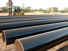
Steel Pipe Piles and Conical Points

 
CONICAL POINTS FOR PIPE PILES

Steel H Pile Points—Welded

VS00N SERIES H-Pile Points

Versa Steel H-Pile pointes are made of high strength, low alloy cast steel. Cast steel is a superior material choice because it’s isotropic – its properties are uniform in all direction. Cast steel points absorb impact and transfer it uniformly to the end of the pile
Tips are pre-beveled, eliminating pile end preparation. The weld prep is already built into the point, our castings have a 45 degree weld chamfer so there is no need to chamfer piles.


Weld procedure

1. To insure proper seating of the tip, remove all flash from end of pile and insert tip.
2. Using a 70xx series rod, make a single pass weld (see table) across each flange on the outside only.
3. Do not weld web or inside of flanges.
4. For heavier sections, you may want to use multiple welding passes.

Steel H Pile Splices—Bolted and Welded

Welding Procedure

1. Cut 1.0" wide x 1.0" long notch in center of web of one pile.
2. Chamfer outside edges of flanges on ends of one or both piles to be spliced. Make chamfer to about ½ material thickness.
3. Insert splicer on first pile making sure bolt is completely inside notch.
4. Install next section of pile and tighten bolt.
5. Using a 70xx series rod, weld the flanges of splicer to the flanges of the pile with (TABLE)" by 3" vertical fillets.
6 Weld the outside flanges of the piles to complete.

Tuesday, October 26, 2010

Timber Piles - Specifcations

Treated timbers are used in marine applications where they will remain submerged below water level to preserve their life. Timber piles are also used by homebuilders in areas where subsurface water is close to the surface and the underlying soils will not support a conventional foundation.

Specifcations

Section 4165. Timber Piles.
4165.01 DESCRIPTION.
Timber piles shall be round sections of the trunks of trees trimmed, peeled, and with or without preservative treatment. They shall meet the requirements for the class of piles specified in the contract documents.
Inspection arrangements shall be in accordance with Materials I,M. 462. The cost of inspection shall be included in the unit price bid for the material specified.

4165.02 CLASSIFICATION.
Piles shall be classified as follows, according to the use for which they are intended:

A. Untreated Timber Piles.
Untreated timber piles may be used for falsework or temporary construction.

B. Treated Timber Foundation Piles.
Treated timber foundation piles will be used for permanent foundations and for permanent wood substructures above groundwater level, unless treated timber trestle piles are specified in the contract documents.

C. Treated Timber Trestle Piles.
Treated timber trestle piles shall be used for permanent wood trestle and may be specified for piers and abutments of substructures, where the more restrictive straightness requirements of this class are desirable.

4165.03 UNTREATED TIMBER PILES.
Timber piles to be used where preservative treatment is not required may be White Oak, Burr Oak, Cypress,
Tamarack, Douglas Fir, Southern Pine, or other wood which will satisfactorily withstand driving. They shall meet the following requirements:
A. General Quality.
Piles shall be cut above the ground swell from live, sound, solid trees and shall have a gradual taper from point of butt measurement to tip. They shall be free from ring shakes, decay or rot, unsound knots, soft red heart, splits, and other defects which will impair their strength or durability. Cypress piles showing "peck" more than a single spot equal to 3% of the area of the end will not be accepted. Piles shall be free from excessive checks at the tip which would cause splits in driving.

B. Knots.
Piles shall have no unsound knots. Sound knots will be permitted, provided they are not in clusters, and provided the diameter of any single knot is not larger than 4 inches (100 mm) or 30% the diameter of the pile at the point where it occurs, whichever is smaller. The sum of diameters of all knots in any 1 foot (0.3 m) length of pile shall not exceed 2 times the diameter of the allowable knot. Diameters of knots shall be measured in a plane perpendicular to the long axis of the pile.

C. Rate of Growth.
When measured at the butt, over the outer 3 inches (75 mm) of a radial line from the pith, piles shall show not less than the number of annual rings and percentage of summerwood specified below for the respective species:

SUMMERWOOD
Species
Rings per Inch (25 mm)
Minimum
Douglas Fir
Douglas Fir
Southern Pine
Southern Pine
More than 5
5 or less
More than 5
3 to 5

30%

30%

When the number of annual rings varies along different radii, the average of two or more measurements along representative radii shall be used.

D. Holes.
Holes shall be permitted if less than 1/2 inch (13 mm) in average diameter, if they do not penetrate more than 20% the diameter at the point where they occur, and if the sum of the average diameters of all holes in any square foot (0.1 m2) of pile surface does not exceed 1 1/2 inches (40 mm).

E. Twist of Grain.
Piles shall be free of twist in grain exceeding 50% the average circumference in a 20 foot (6 m) length.

F. Length.
Piles shall be furnished in the length specified in the contract documents or as directed by the Engineer. A variation of 6 inches (150 mm) in length will be permitted, but the average length for piles of any one lot shall be at least equal to the specified length.

G. Straightness.
Piles shall be free from sweep in two planes (double sweep). They shall be free of short crooks. In measuring for short crooks in any 5 foot (1.5m) section, the distance from the center of the pile at the point of greatest deviation to a line stretched from the center of the pile above the bend to the center of the pile below the bend shall not exceed 4% of the length of the bend, or a maximum of 2 1/2 inches (65 mm). In sweep in one direction and in one plane, the center of the pile shall not deviate from a straight line connecting the center of butt with the center of the tip by more than 1.0% of the length of the pile, or 4 inches (100 mm), whichever is greater, with a maximum deviation of 6 inches (150 m) for lengths over 50 feet (15 m). Piles with sweep in two directions in the same plane (reverse sweep) may be accepted, provided the reversal is within the middle half of the length, and provided the deviation of the center of the pile from a straight line connecting the center of the butt with the center of the tip does not exceed 2 inches (50 mm). Within 25% of the length of the pile, but not less than 10 feet (3 m) nearest the tip, the center of the pile shall not deviate more than 1 inch (25 mm) from a line drawn from the center of the pile above this length to the center of the tip.
H. Dimensions.
At least 95% of the pieces of one length in any one shipment shall conform to the following dimensions for the species of wood specified. The remaining 5% of the pieces may be deficient in diameter at tip or 3 feet (1 m) from butt by not more than 1/2 inch (13 mm).

Win. Diameter 3 Feet (1 m) From Butt

Min. Tip Diameter
inches (mm)
Length
feet (m)
Fir & Pine
inches (mm)
Other Species
inches (mm)
20 and shorter (6.0)

10* (250*)

10* (250*)

8 (200)

25 to 30 (7.5 to 9.5)

11 (275)

11 (275)

8 (200)

35(10.5)

12 (300)

13 (325)

.8(200)

40 (12.0)

12(300)

13 (325)

7(175)

40 to 60 (13.5 to 18.0

1 3 (325)

14(350)

7(175)

over 60 (18.0)
13(325)
14(350)
6(150)
'Measured at the butt.

Advantages and Disadvantages of Different Types of Piles


Wood piles
+The piles are easy to handle.
+Relatively inexpensive where timber is plentiful.
+Sections can be joined together and excess length easily removed.
–The piles will rot above the groundwater level. Have a limited bearing.
–Can easily be damaged during driving by stones and boulders.
–The piles are difficult to splice and are attacked by marine borers in salt water.

Prefabricated concrete piles (reinforced) and prestressed concrete piles affected by the
ground-water conditions.
+Do not corrode or rot.
+Are easy to splice. Relatively inexpensive.
+The quality of the concrete can be checked before driving.
+Stable in squeezing ground, for example, soft clays, silts and peats pile material can be inspected before piling.
+Can be re driven if affected by ground heave. Construction procedure unaffected by groundwater.
+Can be driven in long lengths. Can be carried above ground level, for example, through water for marine structures.
+Can increase the relative density of a granular founding stratum.
–Relatively difficult to cut.
–Displacement, heave, and disturbance of the soil during driving.
–Can be damaged during driving. Replacement piles may be required.
–Sometimes problems with noise and vibration.
–Cannot be driven with very large diameters or in condition of limited headroom.

Driven and cast-in-place concrete piles
Permanently cased (casing left in the ground)
Temporarily cased or uncased (casing retrieved)
+Can be inspected before casting can easily be cut or extended to the desired length.
+Relatively inexpensive.
+Low noise level.
+The piles can be cast before excavation.
+Pile lengths are readily adjustable.
+An enlarged base can be formed which can increase the relative density of a granular founding stratum leading to much higher end bearing capacity.
+Reinforcement is not determined by the effects of handling or driving stresses.
+Can be driven with closed end so excluding the effects of GW.
–Heave of neighboring ground surface, which could lead to re consolidation and the development of negative skin friction forces on piles.
–Displacement of nearby retaining walls. Lifting of previously driven piles, where the penetration at the toe have been sufficient to resist upward movements.
–Tensile damage to unreinforced piles or piles consisting of green concrete, where forces at the toe have been sufficient to resist upward movements.
–Damage piles consisting of uncased or thinly cased green concrete due to the lateral forces set up in the soil, for example, necking or waisting. Concrete cannot be inspected after completion.
Concrete may be weakened if artesian flow pipes up shaft of piles when tube is withdrawn.
–Light steel section or precast concrete shells may be damaged or distorted by hard driving.
–Limitation in length owing to lifting forces required to withdraw casing, nose vibration and ground displacement may be a nuisance or may damage adjacent structures.
–Cannot be driven where headroom is limited.
–Relatively expensive.

Bored and cast-in-place (non-displacement piles)
+Length can be readily varied to suit varying ground conditions.
+Soil removed in boring can be inspected and if necessary sampled or in-situ test made.
+Can be installed in very large diameters.
+End enlargement up to two or three diameters is possible in clays.
+Material of piles is not dependent on handling or driving conditions.
+Can be installed in very long lengths.
+Can be installed without appreciable noise or vibrations.
+Can be installed in conditions of very low headroom.
+No risk of ground heave.
–Susceptible to “waisting” or “necking” in squeezing ground.
–Concrete is not placed under ideal conditions and cannot be subsequently inspected.
–Water under artesian pressure may pipe up pile shaft washing out cement.
–Enlarged ends cannot be formed in cohesionless materials without special techniques.
–Cannot be readily extended above ground level especially in river and marine structures.
–Boring methods may loosen sandy or gravely soils requiring base grouting to achieve economical base resistance.
–Sinking piles may cause loss of ground I cohesion-less leading to settlement of adjacent structures.

Steel piles (Rolled steel section)
+The piles are easy to handle and can easily be cut to desired length.
+Can be driven through dense layers. The lateral displacement of the soil during driving is low (steel section H or I section piles) can be relatively easily spliced or bolted.
+Can be driven hard and in very long lengths.
+Can carry heavy loads.
+Can be successfully anchored in sloping rock.
+Small displacement piles particularly useful if ground displacements and disturbance critical.
–The piles will corrode.
–Will deviate relatively easily during driving.
–Are relatively expensive.

Piles—Types


Piles can be classified into three basic types with respect to load transmission and function:

•End bearing piles—those piles that transfer their imposed load onto a firm subsurface stratum.
•Friction piles—those piles that carry their load by the adhesion friction of the soil along the entire surface area of the pile.
•A combination of friction and end bearing.A cast-in-place concrete pile placed via a steel form where a large bulb has been forced into the end bearing bottom.This pile is also known as a Franki pile for its originating company.

Pile foundations can be prepared using timber, steel, concrete, or fiberglass pilings.Each type has a unique characteristic.

Concrete Reinforcing Bar Size/Weight Chart


BAR SIZE
DESIGNATION
WEIGHT
POUNDS
PER FOOT
NOMINAL DIMENSIONS-ROUND SECTION
DIAMETER
INCHES
CROSS-SECTIONAL
AREA-SQ INCHES
PERIMETER
INCHES
#3
.376

.375

.11

1.178

#4
.668

.500

.20

1.571

#5
1.043

.625

.31

1.963

#6
1.502

.750

.44

2.356

#7
2.044

.875

.60

2.749

#8
2.670

1.000

.79

3.142

#9
3.400

1.128

1.00

3.544

#10
4.303

1.270

1.27

3.990

#11
5.313

1.410

1.56

4.430

#14
7.650

1.693

2.25

5.320

#18
13.600
2.257
4.00
7,090
 

Copyright@2010 INGENIERÍA ECONÓMICA